18
LTC4221
4221fa
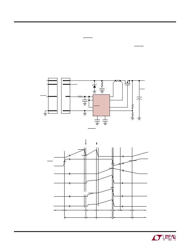
The LTC4221 can also be configured to automatically retry
after a fault condition. As shown in Figure 10, the FAULT
(which has an internal 3.8糀 pull-up current source) and
both ON pins are connected together. The timing diagram
in Figure 11 illustrates a simultaneous start-up sequence
where the LTC4221 is powered up into a load overcurrent
condition on channel 1. After the slow comparators are
armed at the end of the start-up cycle at time point 4, slow
comparator 1 immediately trips and FILTER ramps up.
FILTER ramps past its high threshold at time point 6 and
trips the circuit breaker. FAULT and both ON pins are
pulled low by an internal N-channel MOSFET and over-
shoots below the 0.4V reset threshold of the ON1 pin.
Once ON1 < 0.4V for more than 15約, the internal fault
APPLICATIO S I FOR ATIO
U
U
U
+
V
CC1
ON1
SENSE1
ON2
FAULT
R
F2
15k
LTC4221*
GATE1
FB1
4221 F10
1
16
7
10
9
C
TIMER
1糉
GND
TIMER
R
F1
56k
V
OUT1
3.3V
5A
V
OUT2
2.5V
5A
Q1
IRF7413
R
SENSE1
0.004?/DIV>
C
LOAD1
8
C
FILTER
1nF
FILTER
Z1
Q2: 2N7002LT1
Z1: SMAJ10
* ADDITIONAL DETAILS
OMITTED FOR CLARITY
R
X1
10?/DIV>
C
X1
100nF
C
ON1
0.47糉
R1
1M
LONG
V
CC1
LONG
PCB EDGE
CONNECTOR
(MALE)
SHORT
BACKPLANE
CONNECTOR
(FEMALE)
LONG
V
CC2
FAULT
Figure 10. Using FAULT to Configure Autoretry
2
1
3
4 5
6 7
8
9
20糀
ELECTRONIC CIRCUIT BREAKER ARMED
20糀
2糀
1.8糀
0.4V
0.4V
0.851V
V
FILTER(TH)
V
SENSE(FC)
V
SENSE(SC)
9.5糀
105糀
1.9糀
V
TMR(L)
V
TMR(H)
0.851V
TIMER
ONn, FAULT
FILTER
GATE1
SENSE1
V
OUT1
RESET
CHANNEL
START-UP
FILTER
RAMP
RESET
t
ON
t
INITIAL
OFF
INITIAL
TIMING
4221 F11
INITIAL TIMING
t
INITIAL
t
STARTUP
t
FILTER
SLOW COMPARATORS ARMED
Figure 11. Autoretry Timing Waveforms
发布紧急采购,3分钟左右您将得到回复。
相关PDF资料
LTC4222CG#PBF
IC CTRLR DUAL HOT SWAP 36-SSOP
LTC4223CDHD-2#PBF
IC CNTRLR HOT SWAP DUAL 16-DFN
LTC4224IDDB-2#TRPBF
IC CNTRLR HOT SWAP DUAL 10-DFN
LTC4225IGN-1#PBF
IC CONTROLLER HOT SWAP 24-SSOP
LTC4230CGN#TRPBF
IC CONTRLLR HOT SWAP TRPL 20SSOP
LTC4232CDHC#TRPBF
IC CTLR HOT SWAP 5A 16-DFN
LTC4240IGN#TRPBF
IC CTRLR HOTSWAP CPCI I2C 28SSOP
LTC4241IGN#PBF
IC CTRLR HOTSWAP 3.3V AUX 20SSOP
相关代理商/技术参数
LTC4222
制造商:LINER 制造商全称:Linear Technology 功能描述:Dual Hot Swap Controller
LTC4222_12
制造商:LINER 制造商全称:Linear Technology 功能描述:Dual Hot Swap Controller
LTC4222CG#PBF
功能描述:IC CTRLR DUAL HOT SWAP 36-SSOP RoHS:是 类别:集成电路 (IC) >> PMIC - 热交换 系列:- 标准包装:50 系列:- 类型:热交换控制器 应用:-48V 远程电力系统,AdvancedTCA ? 系统,高可用性 内部开关:无 电流限制:可调 电源电压:11.5 V ~ 14.5 V 工作温度:-40°C ~ 85°C 安装类型:表面贴装 封装/外壳:10-TFSOP,10-MSOP(0.118",3.00mm 宽) 供应商设备封装:10-MSOP 包装:管件
LTC4222CG#TRPBF
功能描述:IC CTRLR DUAL HOT SWAP 36-SSOP RoHS:是 类别:集成电路 (IC) >> PMIC - 热交换 系列:- 产品培训模块:Lead (SnPb) Finish for COTS
Obsolescence Mitigation Program 标准包装:119 系列:- 类型:热交换控制器 应用:通用型,PCI Express? 内部开关:无 电流限制:- 电源电压:3.3V,12V 工作温度:-40°C ~ 85°C 安装类型:表面贴装 封装/外壳:80-TQFP 供应商设备封装:80-TQFP(12x12) 包装:托盘 产品目录页面:1423 (CN2011-ZH PDF)
LTC4222CG-TRPBF
制造商:LINER 制造商全称:Linear Technology 功能描述:Dual Hot Swap Controller with I2C Compatible Monitoring
LTC4222CUH#PBF
功能描述:IC CTRLR DUAL HOT SWAP 32-QFN RoHS:是 类别:集成电路 (IC) >> PMIC - 热交换 系列:- 产品培训模块:Lead (SnPb) Finish for COTS
Obsolescence Mitigation Program 标准包装:119 系列:- 类型:热交换控制器 应用:通用型,PCI Express? 内部开关:无 电流限制:- 电源电压:3.3V,12V 工作温度:-40°C ~ 85°C 安装类型:表面贴装 封装/外壳:80-TQFP 供应商设备封装:80-TQFP(12x12) 包装:托盘 产品目录页面:1423 (CN2011-ZH PDF)
LTC4222CUH#TRPBF
功能描述:IC CTRLR DUAL HOT SWAP 32-QFN RoHS:是 类别:集成电路 (IC) >> PMIC - 热交换 系列:- 产品培训模块:Lead (SnPb) Finish for COTS
Obsolescence Mitigation Program 标准包装:119 系列:- 类型:热交换控制器 应用:通用型,PCI Express? 内部开关:无 电流限制:- 电源电压:3.3V,12V 工作温度:-40°C ~ 85°C 安装类型:表面贴装 封装/外壳:80-TQFP 供应商设备封装:80-TQFP(12x12) 包装:托盘 产品目录页面:1423 (CN2011-ZH PDF)
LTC4222CUH-PBF
制造商:LINER 制造商全称:Linear Technology 功能描述:Dual Hot Swap Controller with I2C Compatible Monitoring
